What is a Spaceship?
== This will be removed when I feel the write-up is no longer a work in progress. So treat everything below as inaccurate in math but principled in reasoning. ==
Even over a millenium ago, Vikings did not build longships by cobbling together a bunch of smaller boats yet, in principle, this is how we have built the ISS. By joining several smaller “space boats” together over several years, we managed to get a long-duration habitable vessel greater than its parts. But its modular architecture, dictated by the reusable (and, compared to the Saturn V, drastically less capable) Space Shuttle , is also why we have been stuck with single-digit occupancy space stations since the first space station 1. Contrasting again to the crew sizes of 11th-century longships, which were double-digit occupancy—ranging from 30-40—it’s hard to not think that something was fundamentally mistaken about this approach.
With this ship-building analogue, when I revisited a chartRecreated below with clearer categories and more examples. visualising crew sizes against comfort for real, planned, and conceptual space stations while answering Where is my von Braun Wheel? I now saw more than the architectural/technical issues with modular construction. I now saw issues with terminology.
After all, a boat is not also called a ship.
A kayak is also not mistaken for a ship, even if some classify them (not incorrectly) as boats.
For far too long I, like much of the community, had lazily used the space station misnomer as a catch-all for all of these clearly different orbital pressure vessels. Sometimes, we also call them spacecraft and satellites. These are all correct terms but simultaneously imprecise, not just in terms of their scales and capacity but also in how we imagine them being manufactured/constructed.
Now, as I revisited the work of these engineers at Langley, it was increasingly evident that these engineers should have called their creations as spaceshipsThe term is implied in science fiction but again, I am not sure what it actually conveys in my limited reading. Maybe someone has been more precise and I am poorly read—let me know, if so. instead of calling them unitised space stations. These non-modular vessels are perhaps the first (and dare I say only) foray into spaceship engineeringMuch like how naval architecture covers shipbuilding but not boat-building. . It is distinct to spacecraft or satellite engineering as I suspect it will help us look at the problem of building them with a fresh set of eyes—not falling into the trap of starting with modularity but introducing its need as and when necessary. It is completely possible that this distinction is only useful to me at this point but I hope that, by the end of this post, I have made a stronger case for spaceship engineering as a field/subfield. It is something I suspect we will need as try to build towards a future with Starship.
%% To me, this is also now allowing a first-order conceptualisation of how we might build spaceships in the near-term; indeed, I am hoping to bias more people away from the modular architectures we have seen so far and migrate towards the “unitised” philosophy of Langley (which we have clearly lost). So let’s look at the plot. %%
What is a Spaceship?
To help you see what I did, I present an updated plot with three regions classifying space pressure vessels as: space stations (what we have built so far); superstructures (what we wish to build); and spaceships (what we need to build next) as the step between them.
A little more on the chart above and the logic of better defining spaceships:
- I use space stations for everything that we have flown so far that we have called a “space station” but allow for crew sizes of upto 25 (arbitrarily chosen but I think this is generous).
- Next, I placed the outlandish (outworldish?) conceptual designs like the Stanford Torus and O’Neill Cylinders to fall under this category and call this region as space superstructuresI have kept adding to the list from the earlier post and can see where certain systems fall (like the Bernal Sphere and Kalpana One). . Now, something the plot doesn’t convey but is important to note is that these superstructures inherently assumed needing space resources for their construction. This is untrue for space stations.
- Spaceship territory then is the region between these two categories. In my short-term vision, the need for space resource use in their creation is not a requirement and, to keep things real, should be avoided-however, spaceships are (or should become) platforms from where we launch a variety of missions to asteroids for space resource extraction, which there is no dearth of ideas for so I won’t go into this. As we will see shortly in how to build spaceships, even with terrestrial resources, a lot of R&D to invent/discover new materials is (likely) needed. The delineation between the three categories should not be seen as a precise definition of any of them but purely as a first-principles (or crude?) attempt to define a spaceship by contextualising it as a bridge between reality/realizable systems (space stations) and what is currently strictly fantasy (superstructures). Perhaps, this categorisation enables even more precise definitions—if it helps narrow the scope of newer, better, and cheaper ways engineer larger orbiting pressure vessel, then that can only be a good thing.
Ideal Spaceship
The chart shows an ideal spaceship as a 70-person artificial gravity one with 90 \(m^3\) of habitable volume per person, resulting in an overall habitable volume of 6300 \(m^3\). These values were chosen so as to offer an OOM increase in crew size to the ISS (assumed to be 7) while offering the kind of comfort of Skylab, which was the best in class for a space station (as per the chart). Some comments on the ideal spaceship follow.
- Uses in various gravity conditions: An issue with identifying an “ideal spaceship” as one with artificial gravity and deriving its initial specs from human factors are suggestions that these spaceships are primarily for human occupation. This is not the case. These human factors are merely to help reach a target pressurised volume of 6300 \(m^3\)which is not only comfortable for humans but might also be large enough to be useful for other emerging microgravity applications, like space data centers and in-space manufacturing. It is worth noting that the ideal spaceship’s volume, computed using human factors, does not allude to any pre-determined geometry but is coincidentally close to the pressurised volume of Wernher von Braun’s wheel-shaped space station (80% of which is habitable as per the plot). In his design, the dimensions and corresponding volume are derived from spin rates assumed to be low enough to generate artificial gravity without inducing space motion sickness.
- Geometry and Structural Considerations: However, if we assume that our ideal spaceship is also shaped like a wheel, then the specifications are closer to von Braun’s wheel (with marginally better occupant volume). If we don’t spin the volume, then we still retain a microgravity (or nearly zero-gravity) station for the non-crewed use cases mentioned earlier. Generation of artificial gravity can be thought of as a problem down-stream of achieving larger volumes rapidly; this maybe solved by modular additions of thrusters along the rim or along the spokes connecting the central hub to the rim of the non-spinning volume. But, this is dependent on the materials used to create the rim of the wheel (which we examine below). von Braun assumed this would involve modular robotic assembly from small modules but the Langley engineers later showed other more effective options albeit at smaller scales (e.g., Hexagonal Station in above chart): either using folded rigid deployables or inflatables. The latter would be more ideal as they are more volumetrically efficient than rigid components when it comes to stowing in launch vehicles.
The key engineering idea then is to focus on creating the technology that leads to rapid large volume deployments in Low Earth Orbit with multiple lucrative uses in microgravity and which could then be improved upon for artificial gravity applications.
How to (maybe) make them?
This post uses a summary of somewhat recent work on inflatable stations to identify some challenges to realising large inflatable structures.
Multilayer Inflatable Shell Structure
Shell Challenges
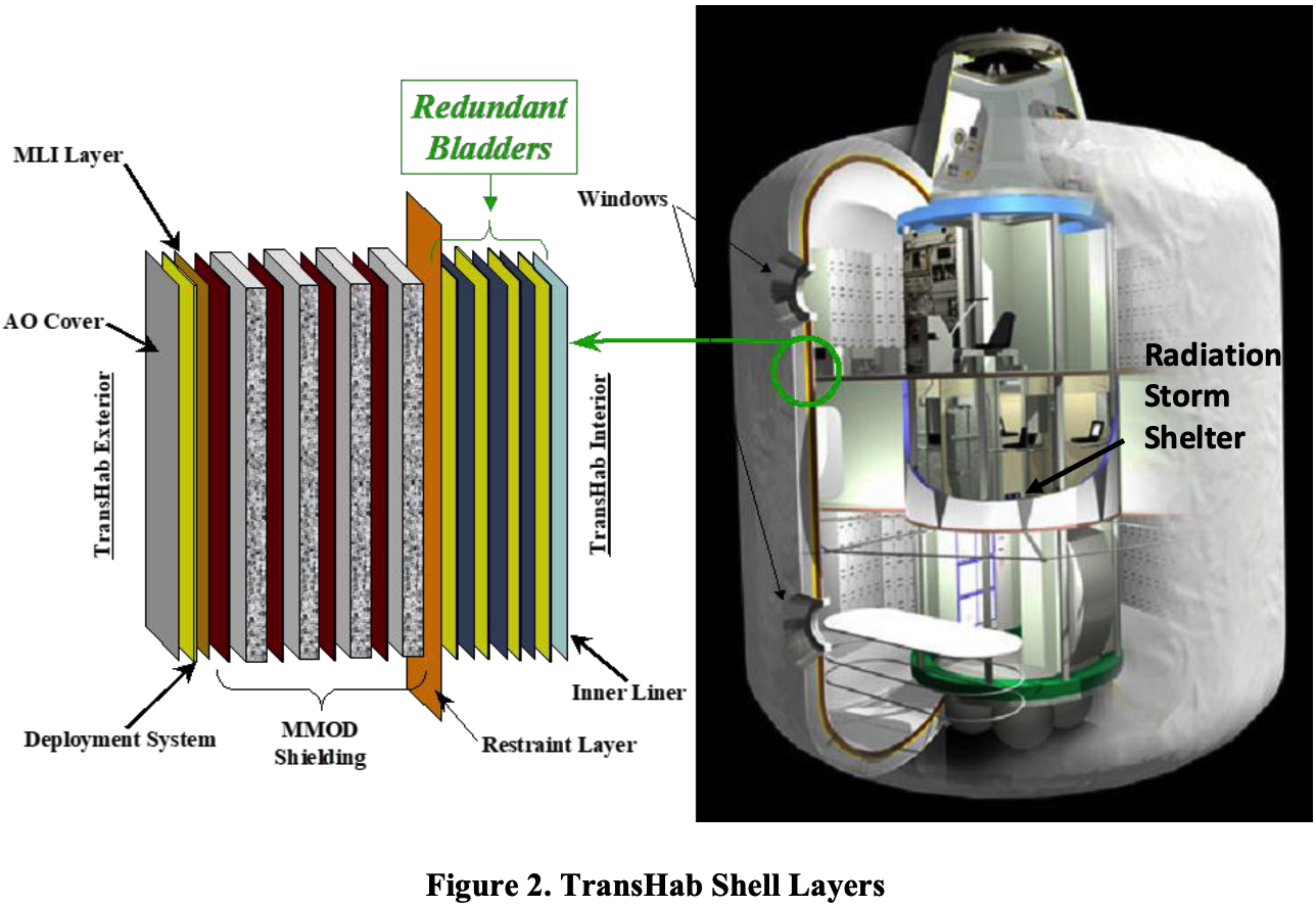
- It comprises five main parts, as shown in the figure below: 1) inner liner layer, 2) bladder layer, 3) restraint layer, 4) micrometeoroid/orbital debris (MMOD) protection layer, and a 5) thermal protection (MLI) layer.
- Much of the focus here will be on the restraint layer, which is main load-bearing layer for the structure and, as will be shown, in need of material innovation as the spaceship scales. There will also be some consideration on the MMOD shields as that can be the bulkiest part of the spaceship, depending on its orbit.
- Vectran was used in making BEAM’s restraint layer that bears loads and stresses at design pressures, which is a multiple (called “factor of safety”) of the operational pressure. 14.7 psi for the ISS and presumed to be the case for any spaceship, as well.
- Now, Vectran’s is five times stronger than steel and ten times stronger than aluminium while being half as dense (1400 \(kg/m^3\)) as aluminium, which means we can get a lot more of it into space. If made purely from Vectran, a 5000 \(m^3\) von Braun wheel would need 7000 tons of Vectran—one such spaceship would require a crazy number of Starship launches: 70!
- Luckily, systems such as TransHab and BEAM were made from 5 layers which result in a far less dense structure when inflated (synonymous with pressurised) as per the table below from the same paper.
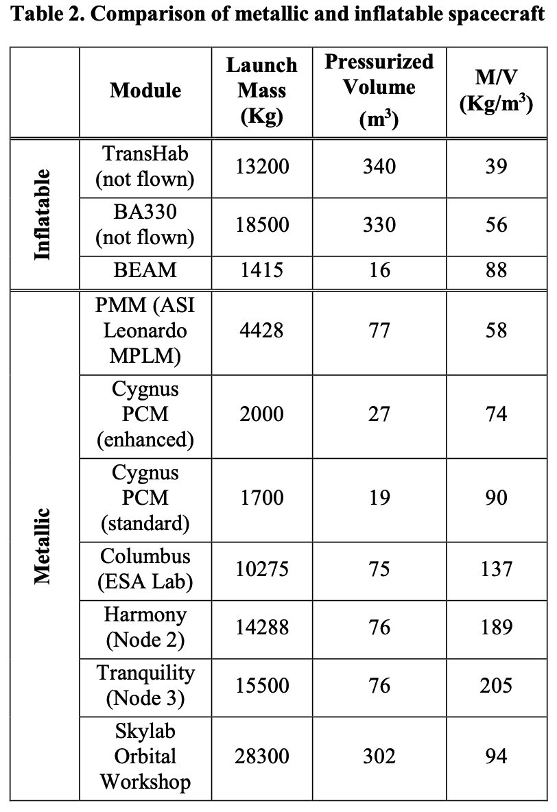
- So, if made from TransHab materials, a 5000 \(m^3\) von Braun wheel would be about 195 tons, which would need only 2 Starship launches and 5 launches if made from BEAM-style materials.
- A next-generation multilayer design that could fit in one Starship launch helps frame the first challenge as:
- BEAM’s density when inflated is 88 \(kg/m^3\) (from above table) and, assuming it’s a cylinder when deflated too, it’s density is 157 \(kg/m^3\). TransHAB is even more impressive with a packaged/deflated/unpressurised density of 122 \(kg/m^3\).
- This also tells us that the compression ratios (pressurised to unpressurized volumes) for TransHab and BEAM are 3.12 and 1.78, respectively.
Restraint layer materials
- Then there is the issue that the TransHab materials only scale to a certain diameter of about 8.2 \(m\)—a von Braun wheel of 75 \(m\) diameter is unexplored territory but the graph suggests that novel restraint materials are needed beyond the 9 \(m\) mark. This is where AI-led materials discovery will become crucial.
- The chart below shows design Categories by Complexity:
- Left side: Simple bladder designs (small, low-load applications)
- Middle: Combined restraint systems
- TransHab sits here: “Bladder + Close Proximity Restraint” at ~20 ft diameter
- Right side: “Novel Restraint System” for very large structures (BA 2100)
Note that cylindrical hoop stress is calculated using pressure (\(P\)), diameter \(D\), and thickness of the habitat \(t\).
\[\sigma_{hoop} = \frac{PD}{2t}\]where restraint layer load per unit length is given by
\[\frac{F}{L} = \frac{PD}{2}\]or
\[\sigma_{hoop}t = \frac{F}{L}\]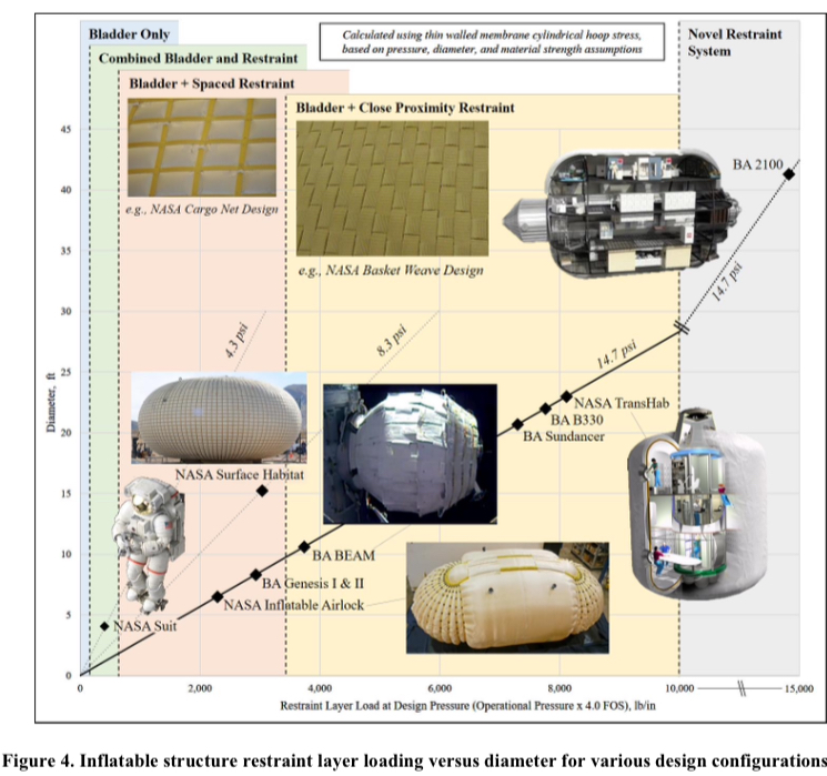
Now this chart above tells us that the loads experienced per unit length of the restraint layer increases with the diameter of the cylindrical shell—the loads on something larger than TransHab can be calculated but we see that the restraint system for it was “novel” (unclear what that means as I haven’t yet searched for/found information on it).
Further, how this behaviour looks like for a toroidal structure in practice is not known—I haven’t done my research to determine this for toroids. But this might mean that we are now not only dealing with scaling issues but also with material issues—what works on cylinders at a specific diameter might not necessarily work on toruses. So I separate this into two challenges below (based on scale, as well as geometry).
MMOD layer
- This layer is 68% of TransHab’s mass for LEO applications, given the higher debris density, but drops to 14% in deep space (what is it for higher Earth orbits?).
- Our chosen orbit is initially assumed to be LEO—to take maximal mass to orbit using Starship’s current specs—there may be a need for in-orbit assembly of Whipple Shield panels around the restraint layer. If this is the case, then perhaps operating in a higher orbit might be preferable. The study should reveal this.
- But the orbit won’t be driven by the spaceship’s engineering challenges alone—market demands of a large data center or robotic factory might show that their desired orbits are more lucrative than crewed spaceships in the near-term.
- Advanced composites: Carbon fiber restraint layers vs. Vectran/Kevlar.
- Hybrid design: More efficient hard-structure to soft-goods ratios.
Comments on Propulsion Systems
I skimmed several papers on rotating habitats and other literature on inflatable structures and saw that there is not really much work explaining how these problems can be solved. So I summarised some of my own ideas/perspectives and fed that into [[ Claude to generate a Research Report on Propulsion and AOCS ]] using the new deep research feature. I still need to read this report but then got Claude to synthesise both my ideas and its findings into another document, which is here [[ propulsion and orbit control for rotating wheel stations ]].
-
A different analogue might have been with aircraft construction—we don’t build an Airbus A380 by stitching together several Cessnas—but I sense there is something more evocative about comparing to a 1000-year old approach to building. Also, several boats are more likely to float but several Cessnas will never leave the tarmac. ↩
Notes mentioning this note
There are no notes linking to this note.